Product Specifications
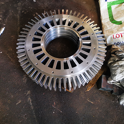
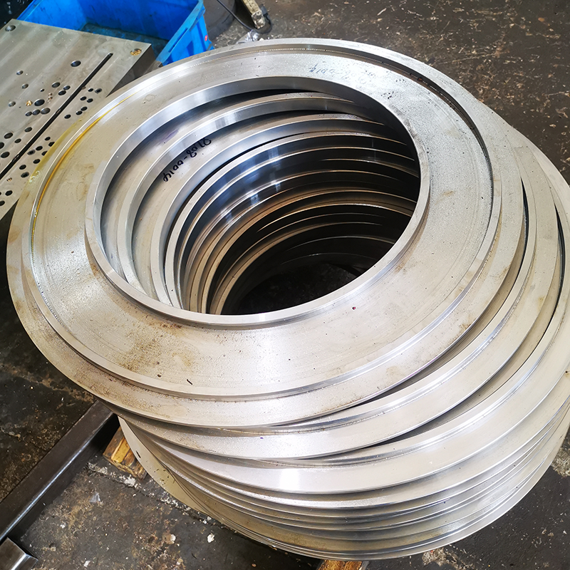
Material: High-strength alloy steel
Surface coating type: Anti-corrosion coating
Tolerance range: ±0.01mm
Processing method: Precision forging and gear grinding technology
Quality inspection: Coordinate measuring instrument inspection
Gear transmission is a mechanical transmission that uses the teeth of two gears to mesh with each other to transmit power and motion. Among all mechanical transmissions, gear transmission is widely used and can be used to transmit motion and power between two shafts that are not far from each other.
Characteristics of gear transmission:
• High efficiency. Among commonly used mechanical transmissions, gear transmission efficiency is the highest, and the closed transmission efficiency is 96%~99%, which has great economic significance for high-power transmission;
• Compact structure, smaller space than belt and chain transmission;
• Stable transmission ratio, which is often the basic requirement for transmission performance. Gear transmission is widely used precisely because of this feature;
• Reliable operation and long life. Gear transmission with correct and reasonable design and manufacture and good use and maintenance is very reliable and can last up to 10 to 20 years, which is unmatched by other mechanical transmissions. This is especially important for vehicles and machines working in mines;
However, the manufacturing and installation precision of gear transmission is high, the price is relatively expensive, and it is not suitable for occasions where the transmission distance is too large.
Classification of gear transmission:
Gear transmission can be divided into cylindrical gear transmission, bevel gear transmission, non-circular gear transmission, rack transmission and worm transmission according to the shape of the gear.
Cylindrical gear transmission
A gear transmission used to transmit power and motion between parallel axes. According to the relative relationship between the gear teeth and the gear axis, cylindrical gear transmission can be divided into three types: spur gear transmission, helical gear transmission and herringbone gear transmission.
Cylindrical gear transmission has a wide range of transmission power and speed, with power ranging from less than one thousandth of a watt to 100,000 kilowatts, and speed ranging from extremely low to 300 meters per second.
Meshing characteristics It can be seen from the formation process of the tooth profile surface that when the involute spur gear meshes, the contact line of the tooth profile surface is a straight line parallel to the axis. During the meshing process, the entire tooth width enters and exits the meshing at the same time, and the force on the gear teeth is also suddenly added or removed, so the transmission stability is poor, and the impact and noise are large.
Bevel gear transmission
Bevel gear transmission is a gear transmission between intersecting axes composed of a pair of bevel gears, also known as bevel gear transmission. According to the tooth line shape, bevel gear transmission can be divided into spur bevel gear transmission, helical bevel gear transmission and curved bevel gear transmission, among which spur gear and curved gear are widely used.
Non-circular gear transmission
Refers to a gear transmission in which the pitch surface of at least one gear in the transmission is not a rotating surface.
Rack transmission
The transmission structure of gear and rack. The rack is divided into spur rack and helical rack, which are used in pairs with spur cylindrical gear and helical cylindrical gear respectively; The tooth profile of the rack is a straight line rather than an involute (it is a plane for the tooth surface), which is equivalent to a cylindrical gear with an infinite pitch circle radius.
Worm transmission
It is a transmission that transmits motion and power between two axes interlaced in space. The angle between the two axes can be any value, and the commonly used is 90°.
Worm transmission consists of a worm and a worm wheel, and the worm is generally the active part. Like threads, worms can be right-handed or left-handed, respectively called right-handed worms and left-handed worms. A worm with only one spiral line is called a single-start worm, that is, the worm rotates one tooth when the worm rotates one circle. If there are two spiral lines on the worm, it is called a double-start worm, that is, the worm rotates one circle when the worm rotates two teeth.
According to the tooth profile curve of the gear teeth, it can be divided into involute gear transmission, cycloid gear transmission and circular arc gear transmission. A transmission composed of more than two gears is called a gear train. Gear transmission can be divided into ordinary gear transmission and planetary gear transmission according to whether there are gears with axial motion in the gear train. Gears with axial motion in the gear train are called planetary gears.
Content and requirements of cylindrical gear machining process
The machining process of cylindrical gears generally includes the following contents: gear blank machining, tooth surface machining, heat treatment process, and precision machining of tooth surfaces. In the process of formulating processes, various process plans are often adopted due to differences in gear structure, accuracy level, production batch, and production environment.
The process of formulating gear machining technology can be roughly divided into the following stages:
1) The formation of gear blanks: forgings, bars, or castings;
2) Rough machining: cutting off a significant amount of margin;
3) Semi precision machining: turning, rolling, and gear shaping;
4) Heat treatment: quenching and tempering, carburizing and quenching, high-frequency induction heating and quenching of tooth surfaces, etc
5) Precision machining: precision machining benchmark, precision machining tooth profile
Analysis of Gear Processing Technology Process
1. Selection of benchmarks
The selection of gear machining benchmarks often varies depending on the structural shape of the gears. Gears with shafts mainly use vertex hole positioning; For a hollow shaft, after drilling the center inner hole, position it with the inclined plane of the two end hole openings; When the aperture is large, a conical plug is used. The accuracy of vertex positioning is high, and it can achieve benchmark overlap and uniformity. The following two positioning and clamping methods are often used for machining perforated gears on the tooth surface.
(1) The positioning method of inner hole and end face positioning is based on the positioning of the workpiece’s inner hole, determining the positioning position, and then using the end face as the axial positioning reference and clamping it against the end face. This can make the positioning reference, design reference, assembly reference, and measurement reference coincide, with high positioning accuracy and suitable for mass production. But there is a high requirement for the manufacturing accuracy of the fixture.
(2) When the clearance between the workpiece and the intensifying spindle is large, use a dial gauge to correct the outer circle to determine the center position, and perform axial positioning on the end face, clamping from the other end face. This positioning method has low productivity because each workpiece needs to be calibrated; At the same time, high requirements are placed on the coaxiality of the inner and outer circles of the gear blank, while low requirements are placed on the accuracy of the fixture, making it suitable for single piece and small batch production.
In summary, in order to reduce positioning errors and improve gear machining accuracy, the following requirements should be met during machining:
1) We should choose a unified positioning method with overlapping benchmarks;
2) When locating the inner hole, the fit gap should be minimized as much as possible;
3) The positioning end face and positioning hole or outer circle should be machined in one clamping process to ensure the verticality requirements.
2. Processing of gear blanks
The gear blank machining before tooth surface machining plays a very important role in the entire gear machining process. Because the benchmark used for tooth surface processing and inspection must be processed at this stage, and the proportion of working hours for gear blank processing is relatively large, both improving productivity and ensuring the quality of gear processing must attach importance to the processing of gear blanks.
In the technical requirements of the gear drawing, if it is specified to use the thinning amount of tooth thickness selected by the indexing circle to measure the tooth side clearance, attention should be paid to the accuracy requirements of the tooth top circle, because the detection of tooth thickness is based on the tooth top circle as the measurement benchmark. The low precision of the tooth tip circle will inevitably make the measured tooth thickness unable to accurately reflect the size of the tooth side clearance. Therefore, the following three issues should be noted in this machining process:
1) When using the tooth tip circle as the measurement reference, the dimensional accuracy of the tooth tip circle should be strictly controlled;
2) Ensure the verticality between the positioning end face and the positioning hole or outer circle;
3) Improve the manufacturing accuracy of the gear inner hole and reduce the fit clearance with the fixture spindle;
3. Tooth shape and tooth end machining
Gear profile machining is the key to gear machining, and the selection of its scheme depends on various factors, such as equipment conditions, gear accuracy level, surface roughness, hardness, etc. The commonly used tooth profile machining schemes have been explained in the previous section and will not be discussed here.
The tooth end machining of gears can be done by rounding, chamfering, chamfering, and deburring. As shown in Figures 9-13. Gears that have been chamfered and pointed are prone to meshing during gear shifting, reducing impact. Chamfering can remove sharp corners and burrs at the tooth end. When rounding, the milling cutter rotates and swings along the arc. After machining one tooth, the workpiece moves away from the milling cutter and quickly approaches the tooth end of the next tooth after indexing.
Tooth end machining must be carried out before quenching, usually arranged after rolling (inserting) teeth and before shaving.
4. Heat treatment requirements during wheel processing
In the process of gear machining, the position arrangement of heat treatment process is very important, which directly affects the mechanical properties and cutting ability of gears. Generally, two heat treatment processes are carried out in gear machining, namely blank heat treatment and tooth profile heat treatment
Contact Information for Gear Inquiries
For more information about Gear or to obtain customized solutions, please contact us:
- Contact Person: Frank
- Tel: 86-510-82305188-8060
- Mobile: 86-18605101203
- Mail: frankgu@cmecwuxi.com
- Address: 15-16F, Building A10, No. 777, JianZhu West Road, Binhu District, Wuxi, Jiangsu, 214072. P.R. China
We look forward to collaborating with you and providing robust support and services for your business.

