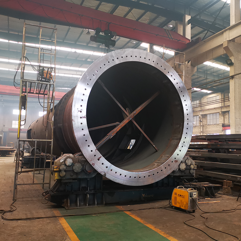
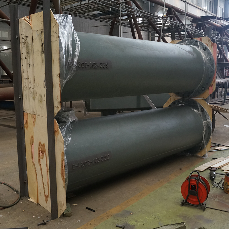
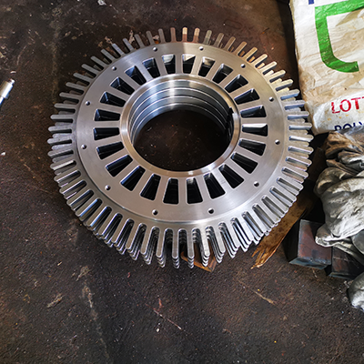
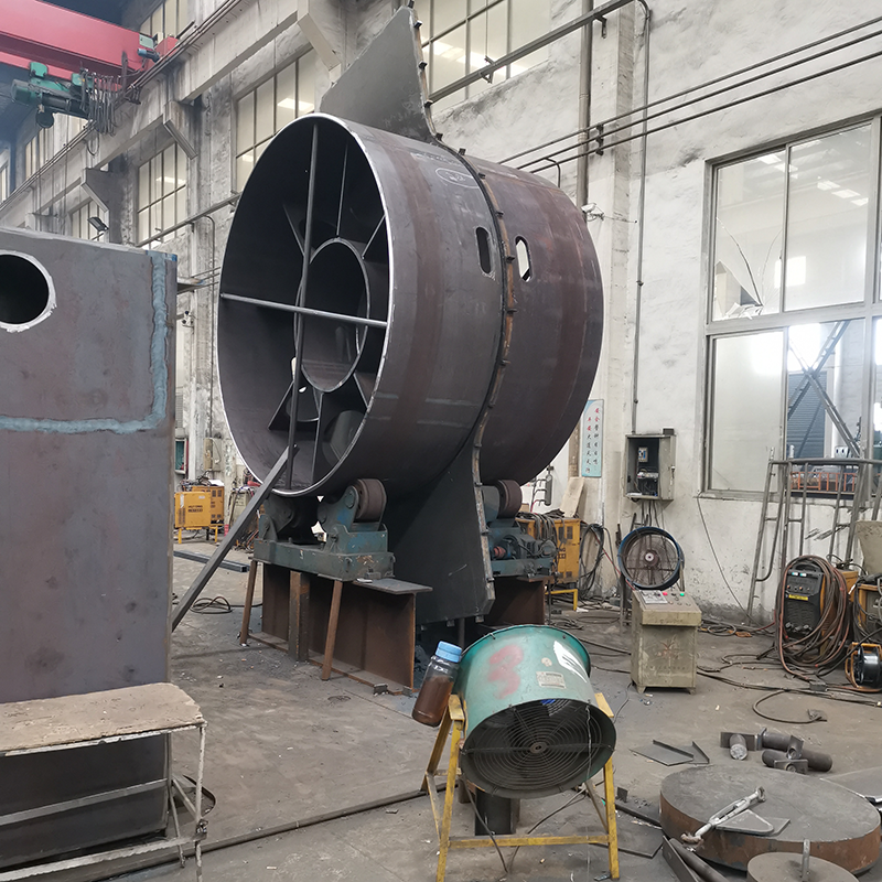
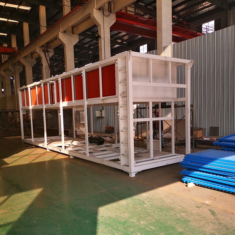
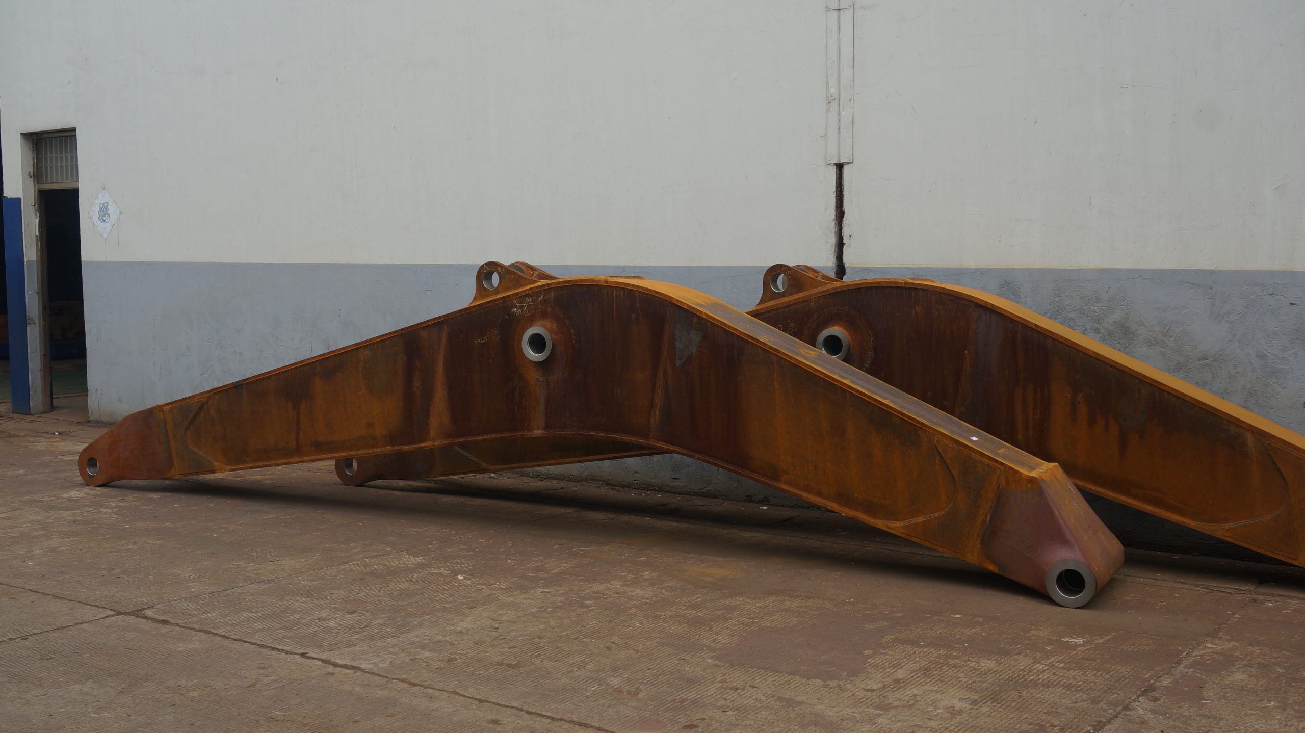
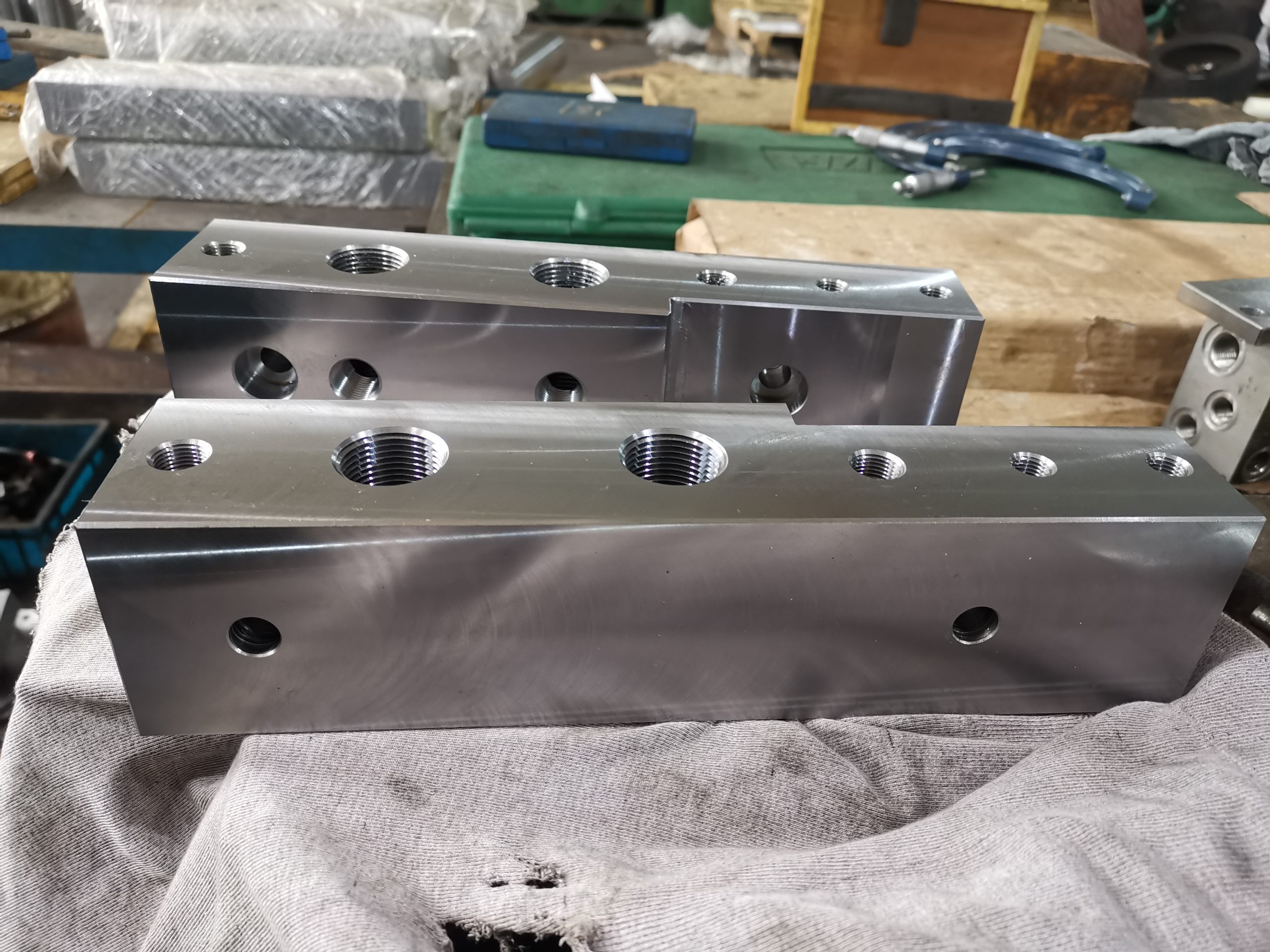
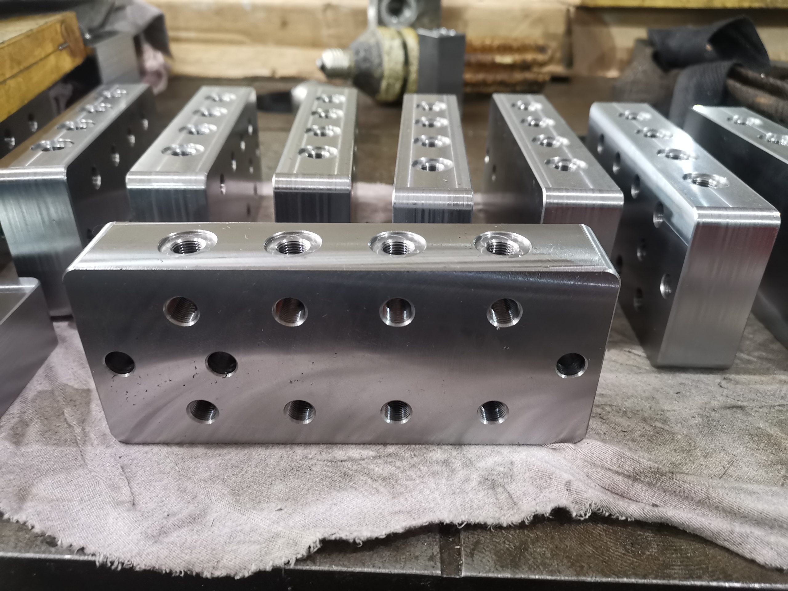
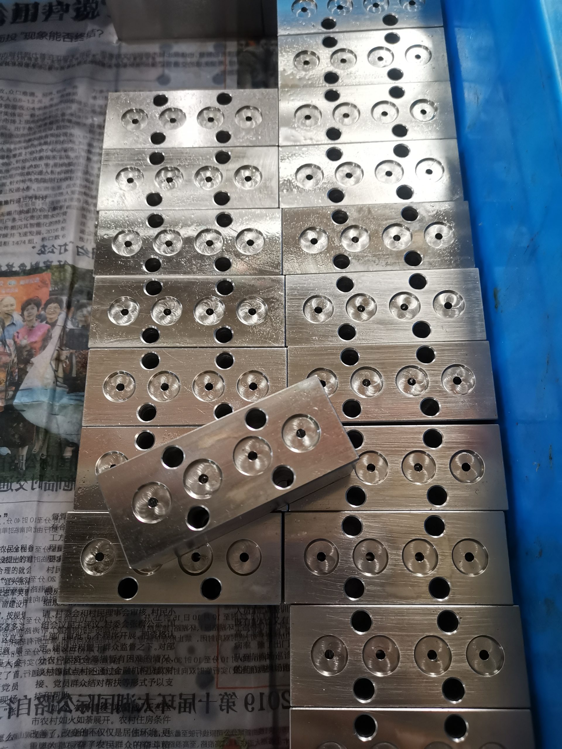
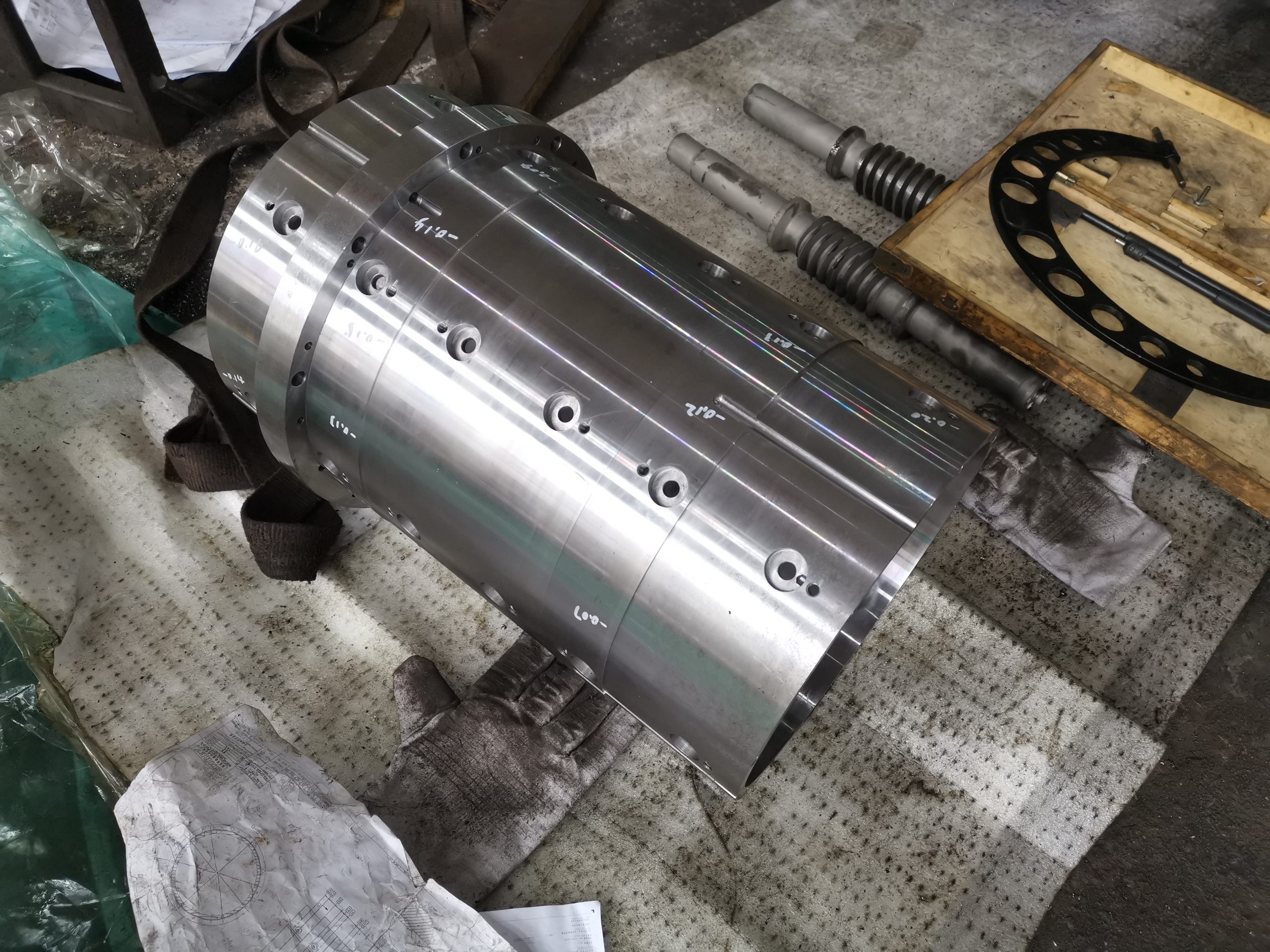
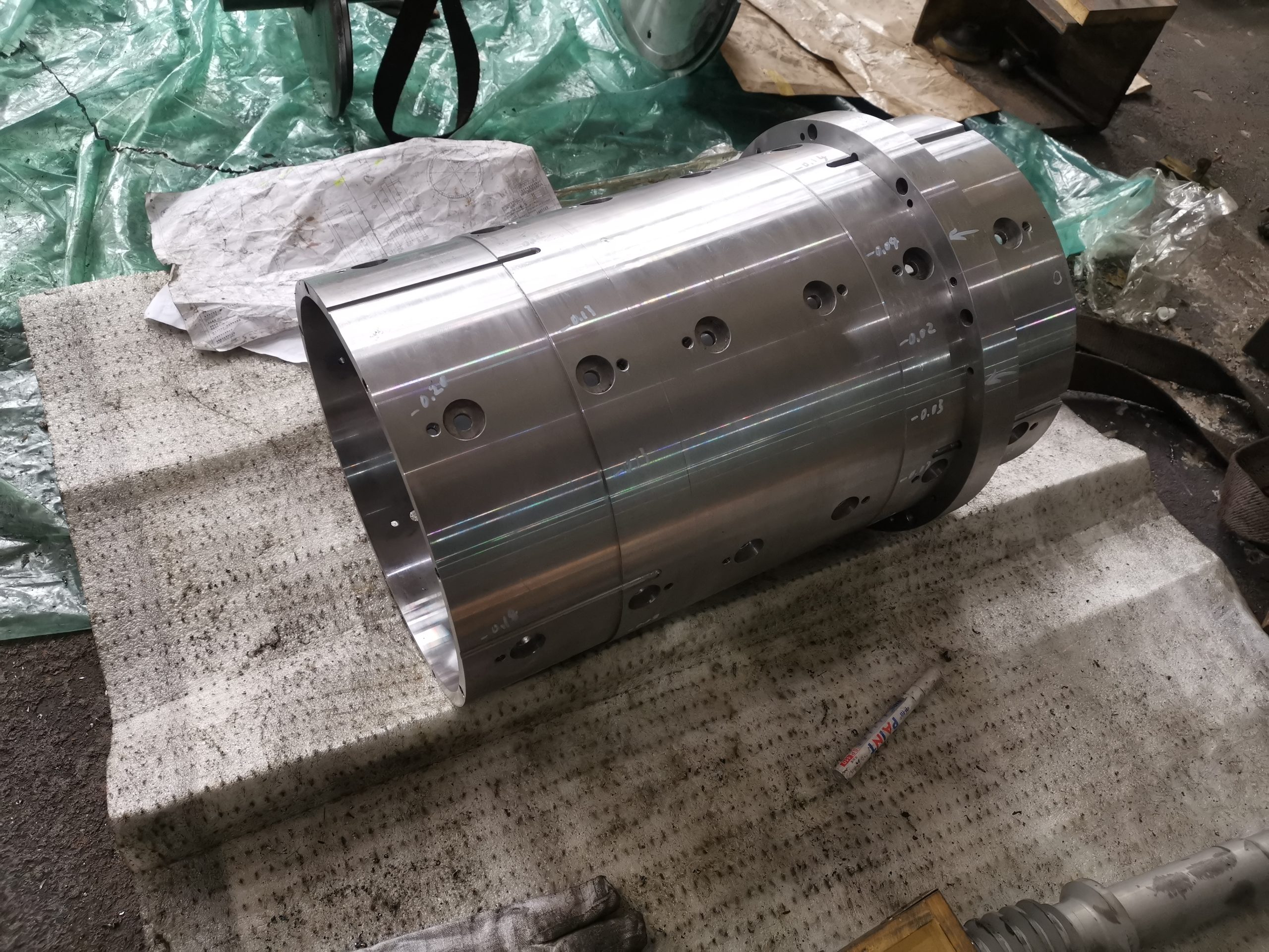
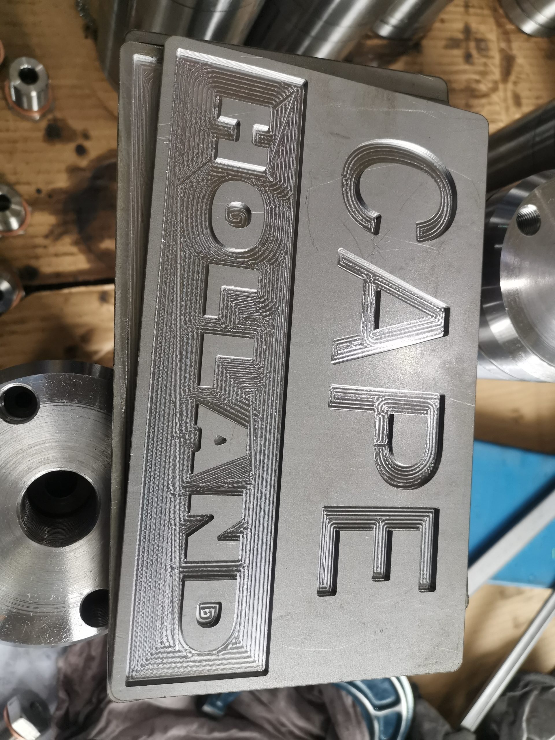
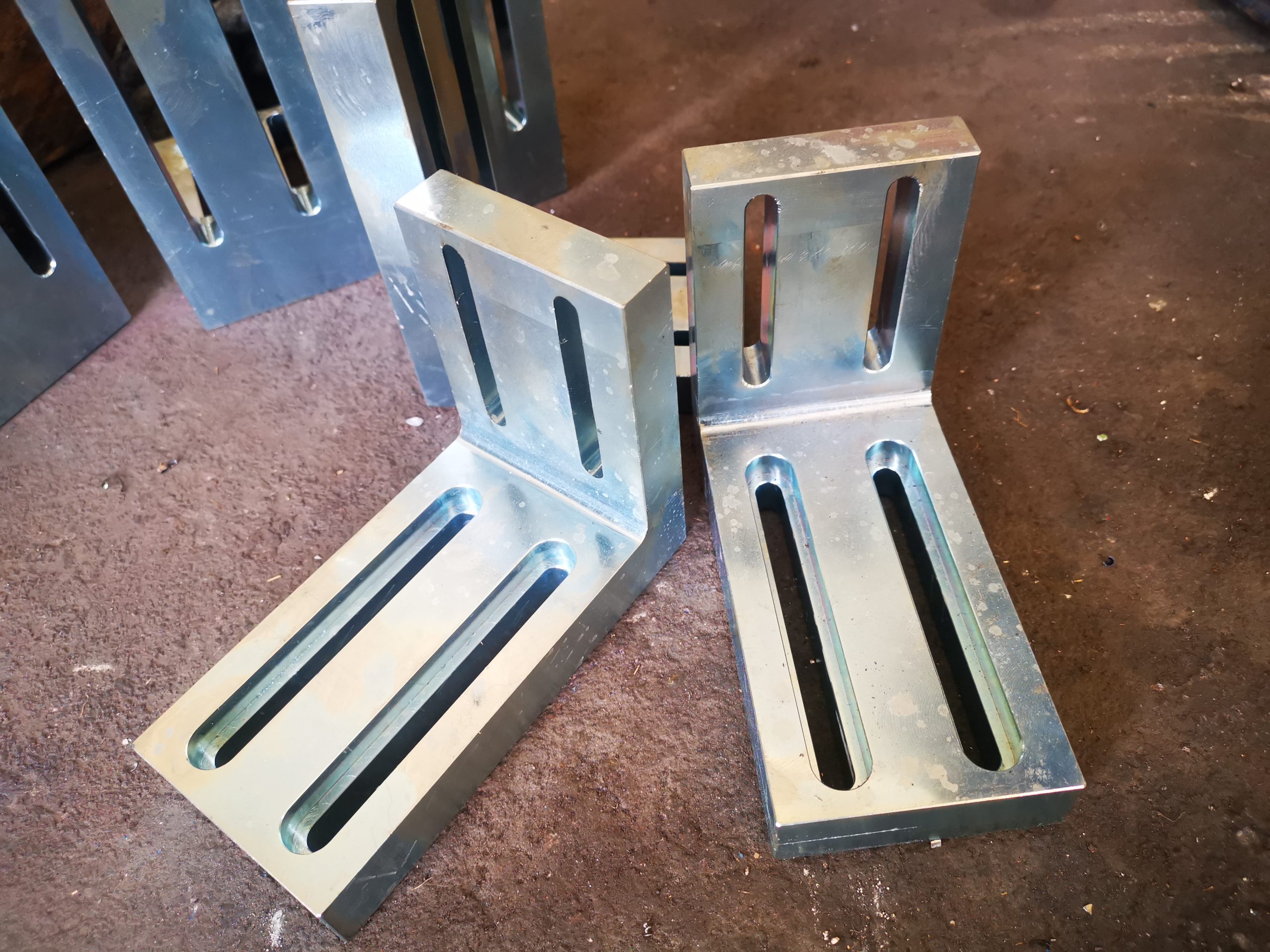
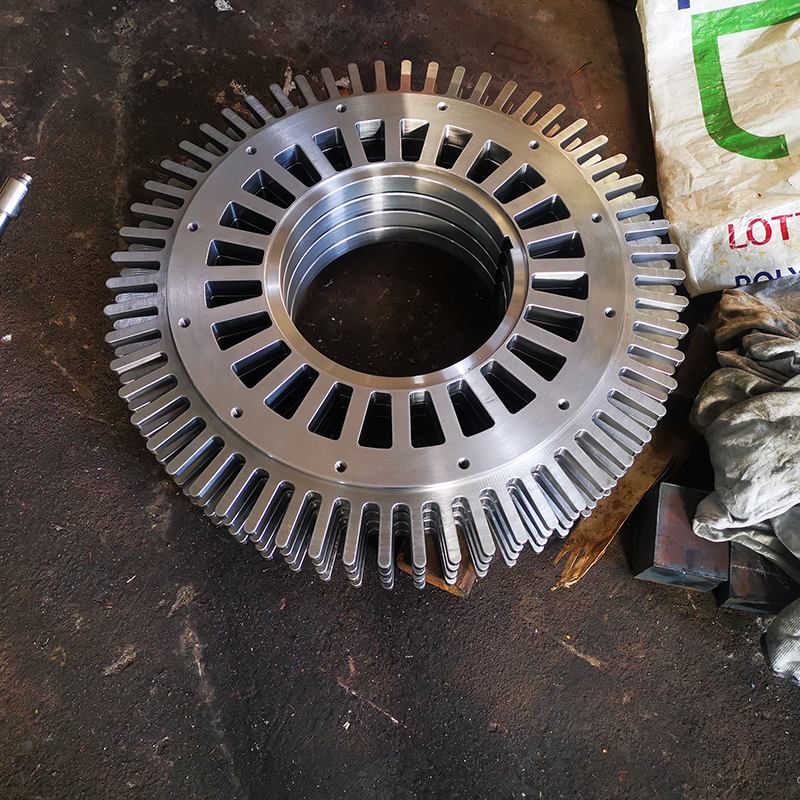
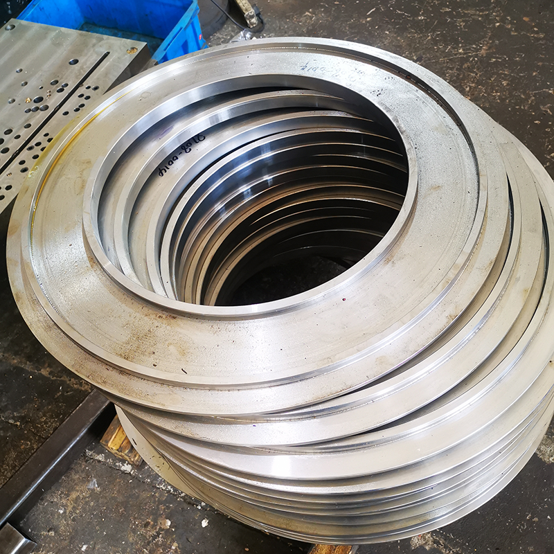
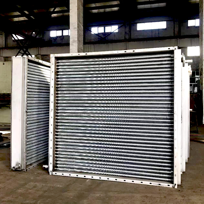
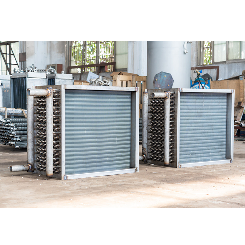
Product specifications
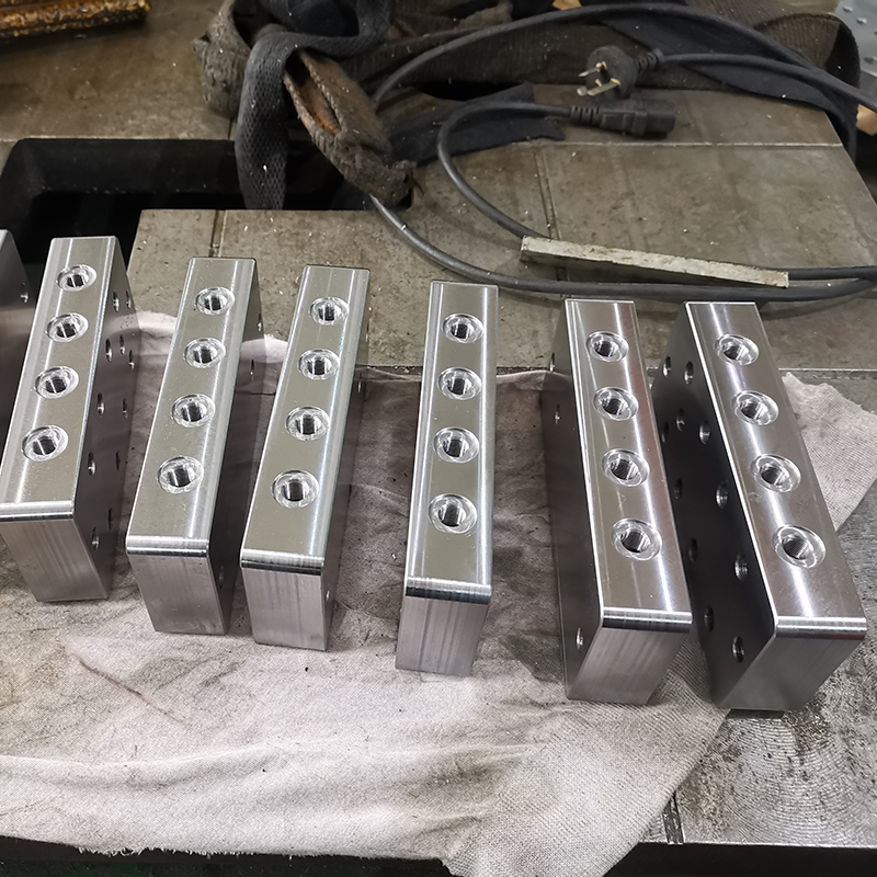
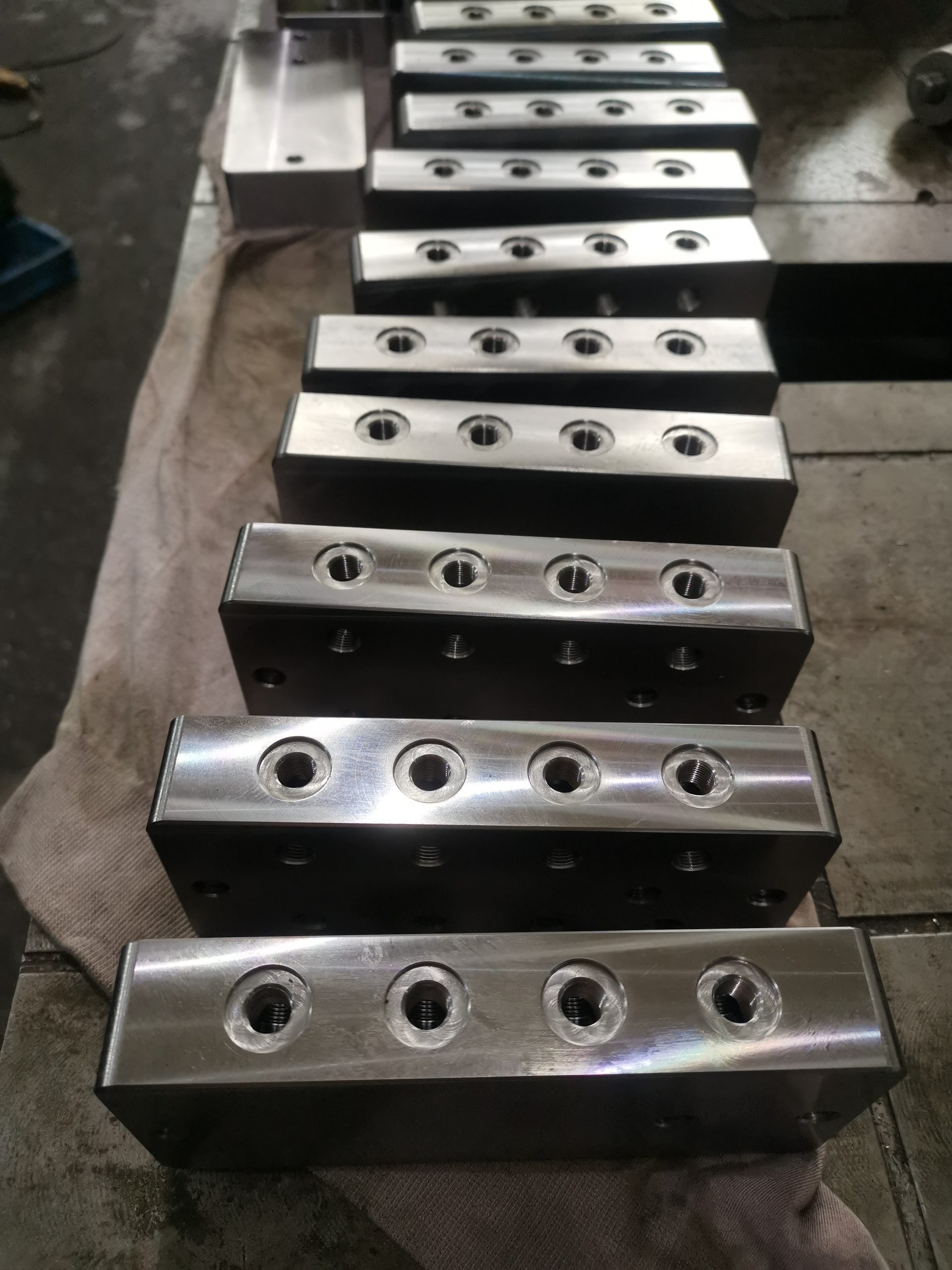
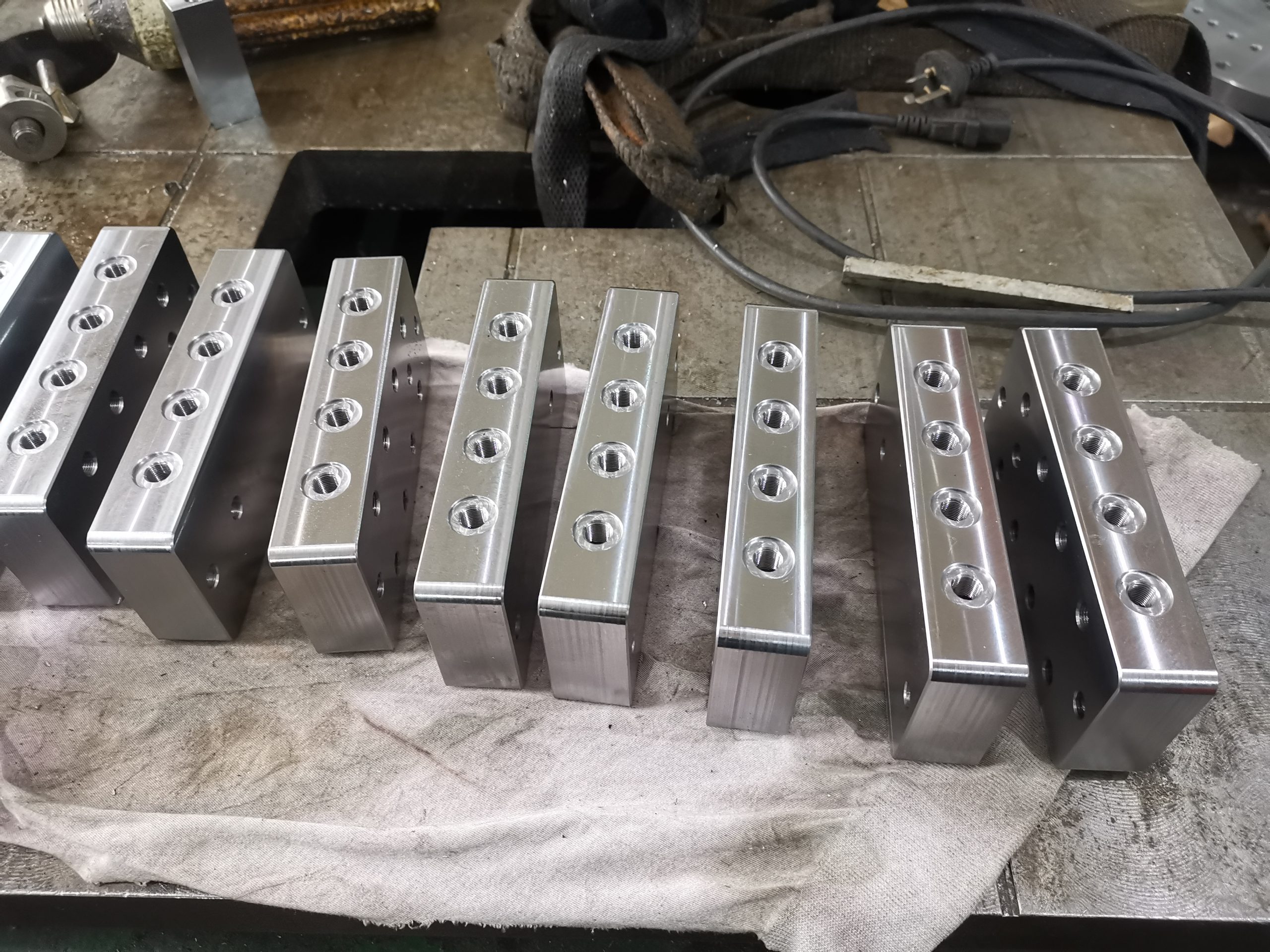
Material: high-strength alloy steel, aluminum alloy, titanium alloy, etc.
Surface coating types: anodizing, galvanizing, chrome plating, etc.
Tolerance range: ±0.005mm
Processing methods: CNC turning, CNC milling, grinding, etc.
Quality inspection: three-coordinate measuring instrument, ultrasonic flaw detector
Structural design specifications for machined parts
1. Pay attention to reducing the size of the blank
2. The machined surface and the unmachined surface should not be flush
3. Reduce the length of the machined surface
4. Surfaces with different machining precisions should be separated
5. Change parts with complex shapes into assemblies for easy processing
6. Avoid unnecessary precision requirements
7. The tool can easily enter or exit the machining surface
8. Avoid machining closed spaces
9. Avoid the tool being unable to approach the workpiece
10. Do not use part structural shapes that are not suitable for the tool shape
11. Consider the impact of casting errors
12. Avoid combined processing of multiple parts
13. Complex The machining surface should be designed on the outer surface rather than the inner surface
14. Avoid chamfering of parts with complex shapes
15. Avoid stopper fit of non-circular parts
16. Avoid unnecessary supplementary machining
17. Avoid part structures that cannot be clamped
18. Avoid part structures without measuring base surfaces
19. Avoid shock and vibration during machining
20. Avoid drilling on inclined surfaces
21. The bottom of the through hole should not be partially undrilled
22. Reduce the number of tools used to machine the same part
23. Avoid multiple fixation during machining
24. Make sure that the part can be machined multiple parts at once
Acceptance requirements for parts in mechanical processing
I. Acceptance requirements
1. Appearance inspection
(1) Check whether the finish of the machined parts meets the requirements of the drawings.
(2) Check whether the surface of the machined parts is damaged, rusted, or dented, and whether the thread shape and angle are correct.
(3) If the above problems are found, detailed records should be made for reference.
2. Quantity acceptance
(1) Based on the supply contract and processing voucher, strictly check the material, specifications, and quantity of the processed parts against the drawings, and check and verify each piece.
(2) Make a record of quantity acceptance, stating the acceptance location, time, participants, type, product name, and expected and actual quantity.
3. Quality acceptance
(1) The assembly must be carried out strictly in accordance with the regulations and procedures required by the general assembly drawings.
(2) Careful records should be kept during quality acceptance. If there are quality problems with the processed parts, the details should be notified to the outsourcing processing unit in writing. Decide whether to return or replace the parts depending on the situation.
(3) If there are special requirements, the processing unit can be consulted for joint acceptance and assembly, and the acceptance document can be signed only after the installation is qualified.
Turning and milling is a method in mechanical processing that combines the characteristics of both turning and milling methods. It is usually used to manufacture complex parts, especially in the automotive, aerospace, and precision machinery industries. Turning and milling can achieve high-precision and complex shape processing requirements, improve production efficiency and processing quality. In turning and milling, the workpiece is fixed on the rotating axis of the machine tool, while the tool is fixed on the workbench of the machine tool. The tool can move along multiple axes to achieve multi axis coordinated machining. By controlling the position and speed of the cutting tool, it is possible to accurately cut the workpiece, thereby obtaining the desired shape and size. Turning and milling machining has the following advantages:
1. High precision: Turning and milling can achieve high-precision machining requirements, with machining accuracy reaching the micrometer level.
2. Complex shape processing: Turning and milling can process complex shapes and structures, such as curved surfaces, holes, protrusions, etc.
3. Improve production efficiency: Turning and milling can achieve multi axis coordinated processing, reduce processing time and intermediate links, and improve production efficiency.
4. Stable quality: During the turning and milling process, the relative position and speed of the tool and workpiece can be precisely controlled to ensure the stability of the machining quality.
5. Suitable for various materials: Turning and milling can be applied to the processing of various materials, such as metals, plastics, ceramics, etc. However, there are also some limitations to turning and milling, such as high equipment costs and the possibility of workpiece deformation caused by the heat generated during the machining process. Therefore, when choosing turning and milling processing, it is necessary to comprehensively consider the actual needs and conditions.
Processing steps:
Step 1:
Firstly, clamp the part onto the lathe chuck and perform surface cutting by vertically moving the tool on the X-axis while the part rotates.
Step 2:
Next is the rough machining operation of the part diameter. This is achieved by moving the tool vertically along the Z-axis. In addition, you can see that smaller diameters have also been machined in the parts.
Step 3:
After selecting a thread cutting tool for tool replacement, thread machining is carried out at the small diameter of the part. This is achieved by moving the tool vertically along the Z-axis in order
Step 4:
The next step is to perform milling operations using a flat end mill with rotational motion as the “power” tool. This tool processes a plane on the cylindrical contour of the part.
Step 5:
After machining a plane on the cylindrical contour of the part, drill holes to generate holes. You will notice that the drill bit has its own rotational motion relative to the parts. The part has stopped rotating!
Step 6:
Next, you can see that a tapping tool has been selected to perform the tapping operation in the hole. This is also a cutting tool that has its own rotation relative to the part.
Step 7:
In the last picture, the drill bit is now ready to machine a set of peripheral holes on the flange of the part. In this case, the lathe chuck serves as a indexing device to correctly position the parts at the correct angle.
Automatic stamping technology is a necessary technical means to reduce the cost of stamping metal parts. The fully automatic stamping production line is a large-scale three-dimensional integrated production line, which can effectively improve the quality of metal parts processing during use, and achieve city wide automation in the processing of parts. Improved the efficiency of parts processing, reduced the demand for raw materials, and reduced the workload of workers, resulting in a significant increase in profits generated by manufacturers in producing metal parts. Therefore, the article explores the application of fully automatic stamping production lines in metal part stamping processing.
Discussion on Fully Automatic Stamping
The formation of stamping began as the most common production method in industrial manufacturing and is widely used in the metal parts manufacturing industry in industries such as home appliances, communication, automotive repair, and IT. At present, most metal parts manufacturers still use traditional metal parts processing methods, which use manual feeding. This method is not only difficult to achieve high production efficiency in the process of metal parts processing, but also has certain safety hazards. It requires a large number of workers to cooperate in order to complete the work. Therefore, this method requires a huge workload of workers. With the continuous reform of the education system, the cultural level of the labor force has also been significantly improved, and the cost of labor has continued to increase. Professional talents with strong work abilities are rare, and a large amount of human resource waste will increase the cost consumption of manufacturers, resulting in a decrease in their economic benefits.
The emergence of fully automatic stamping production lines has perfectly solved the problems existing in traditional manual single machine feeding stamping production. Not only does it reduce the number of workers using it, but it also lowers the production costs of manufacturers, which is an inevitable trend for the future development of metal stamping processing. In recent years, due to the continuous development and progress of information technology and electronic technology, the technology of industrial robots has become increasingly mature. Many developed countries have achieved effective application of fully automatic stamping production lines in metal parts stamping processing during the production process. It has been proven that fully automatic stamping production lines play an important role and significance in the stamping processing of additional metals.
Introduction to 2 Fully Automatic Stamping Production Lines
The fully automatic stamping production line is a large-scale automatic stamping production line that integrates various technologies, and there are multiple precision presses working simultaneously on the production line. The processing and transportation of raw materials can be achieved through motor-driven robotic arms, while the role of fieldbus controlled robotic arms and large precision presses is to monitor and diagnose faults on site, achieving a fully automatic stamping production line during the production of metal parts. For example, in the following figure, the two main machines are connected to metal parts for stamping processing. The robot fully automatic stamping production line is mainly composed of double material exchange and feeding devices, large precision presses, 3D robotic arm feeding devices, servo driven semi feeding devices, etc
The Principle and Application of Fully Automatic Stamping Processing for 3 Metal Parts
3.1 Double accumulation material automatic exchange and feeding device
During the process of automatic exchange and feeding, this device mainly uses the method of separating the workpiece from the material to accurately transport the material to the designated position, so that the three-dimensional feeding system can gradually move the workpiece onto the mold. In the process of stamping metal parts, the three-dimensional feeding system is mainly composed of two parts: a double material automatic exchange device and a feeding device, which can achieve actions in three directions: horizontal and vertical. After using one of the workpieces, automatic replacement of the workpiece pieces can be achieved through the action of a cylinder or hydraulic cylinder, without the need for manual operation.
3.2 Precision mechanical press
Precision mechanical presses are also known as main machines. The processing technology and production process data of metal parts can be entered into the system in advance, and the processing sequence and speed can be set according to the basic requirements of metal parts processing. The replacement of workpiece materials is controlled and coordinated using fieldbus, and the actions between the 3D robotic arm feeding device are always consistent, so that the quality of each process in the metal parts processing can be effectively guaranteed.
3.3 Three dimensional robotic arm feeding device
The 3D robotic arm feeding device is a fully automatic feeding device, which mainly includes feeding, clamping, and lifting. It can achieve movements in three directions: horizontal and vertical, covering the entire space it can touch. In the actual work of metal stamping, the main function of a 3D robotic arm is to support, transport, and shelve materials. Through this method, the materials are transported to designated positions, and the number of hosts, 3D robotic arms, and support seats is adjusted according to the different processing methods of different metal parts. And according to the processing of metal parts and the needs of customers, adjust the feeding speed, change the inherent sequence of part processing, and improve the adjustability of the entire production line.
3.4 Servo driven conveying device
In the process of metal parts processing, if there are many parts that need to be processed simultaneously, installing only one precision press is obviously unable to meet the production needs. Therefore, a servo driven conveying device should be used to transport metal parts that cannot be stamped in a short period of time to the designated location, pick up the materials from the feeding device Pan Songlai one by one, and send them to the main machine for processing one by one. Not only can it handle the pressure borne by precision presses, but it can also increase the speed of metal part processing until the metal part processing is completed, and all stamping processes can be completed (see Figure 2).
From this perspective, whether to use one precision press or multiple precision presses connected in a stamping production line mainly depends on the processing steps required for the metal parts being processed. The servo driven conveying device enables the flexibility of the entire production line to be adjusted at any time, achieving sufficient stamping process for metal parts and improving the quality of the processed metal parts
Greatly improving the application range and service life of related equipment.
The advantages of fully automatic stamping production lines
In the actual processing of metal parts, fully automatic stamping lines are used for stamping processing. Compared to traditional feeding processing methods, the advantages of fully automatic stamping production lines are very obvious: ① Using fully automatic stamping production lines for stamping processing of metal parts can reach a maximum production rate of 25 times per minute, significantly improving its production efficiency. The application of fully automatic stamping production line in metal parts stamping processing can improve the quality of output parts, reduce the cost of metal parts consumption in the production process, and improve the economic benefits of manufacturers The use of fully automatic stamping production lines has reduced the consumption of human resources in traditional production technologies, reduced the area of land resources, and significantly weakened the role and utilization rate of related production equipment. In this way, it can also achieve the effect of reducing production costs and reducing the number of operators. Thus effectively improving the economic benefits obtained by manufacturers in producing metal parts.
Contact Information for custom machined parts Inquiries
For more information about custom machined parts or to obtain customized solutions, please contact us:
- Contact Person: Frank
- Tel: 86-510-82305188-8060
- Mobile: 86-18605101203
- Mail: frankgu@cmecwuxi.com
- Address: 15-16F, Building A10, No. 777, JianZhu West Road, Binhu District, Wuxi, Jiangsu, 214072. P.R. China
We look forward to collaborating with you and providing robust support and services for your business.

