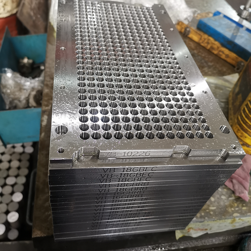
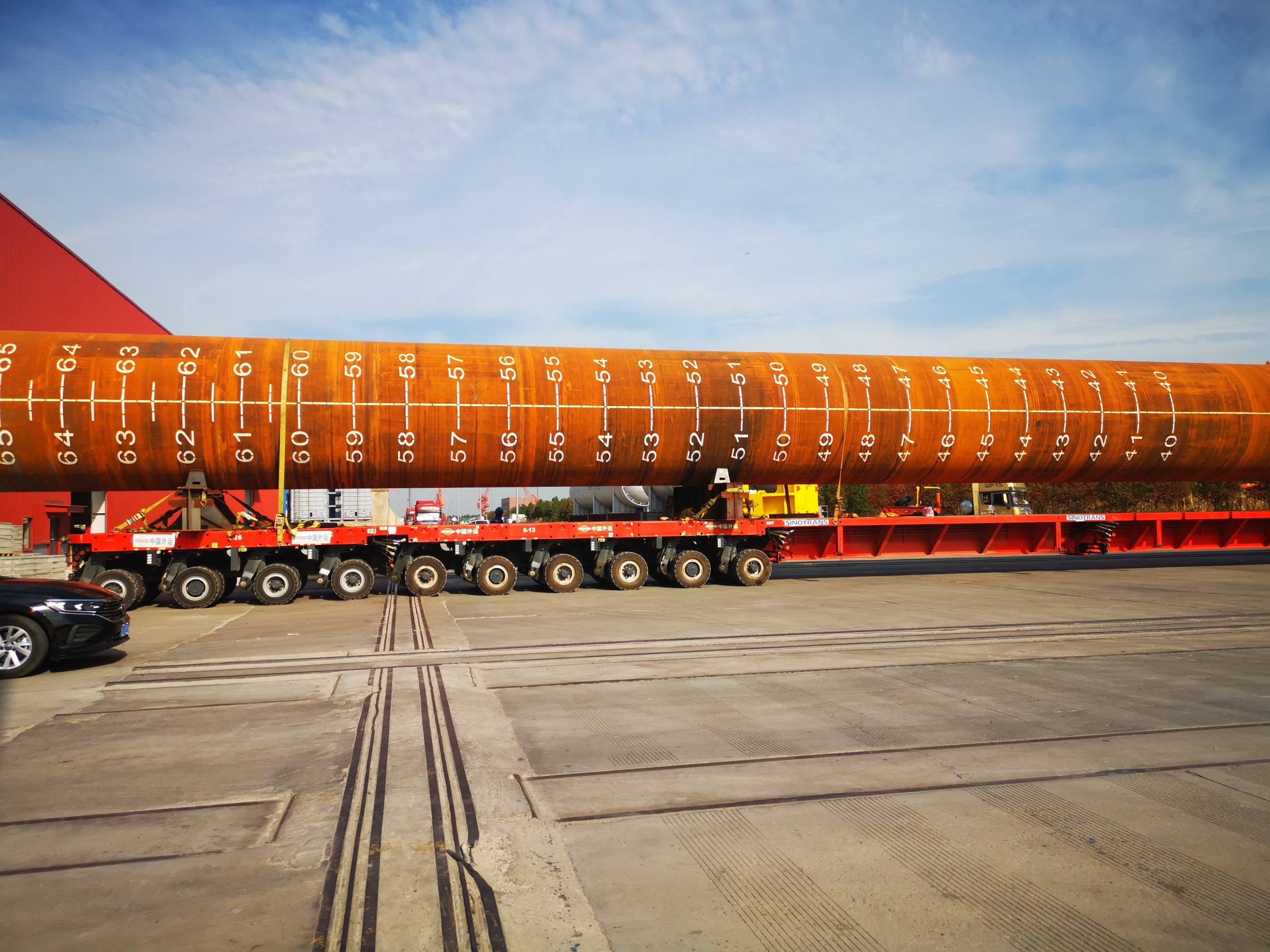
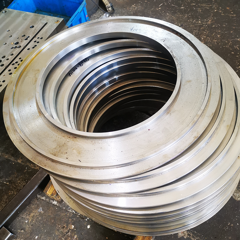
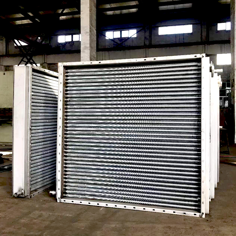
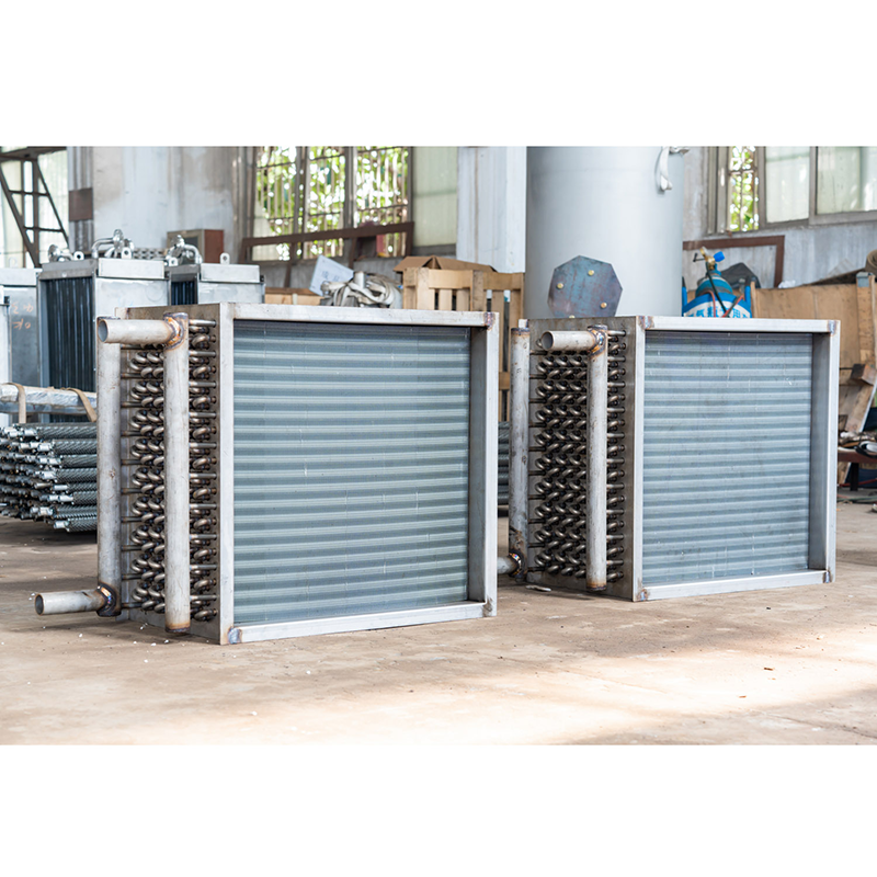
Product specifications:
Material: high-strength steel, corrosion-resistant alloy
Surface coating type: special anti-corrosion coating
Tolerance range: ±0.02mm
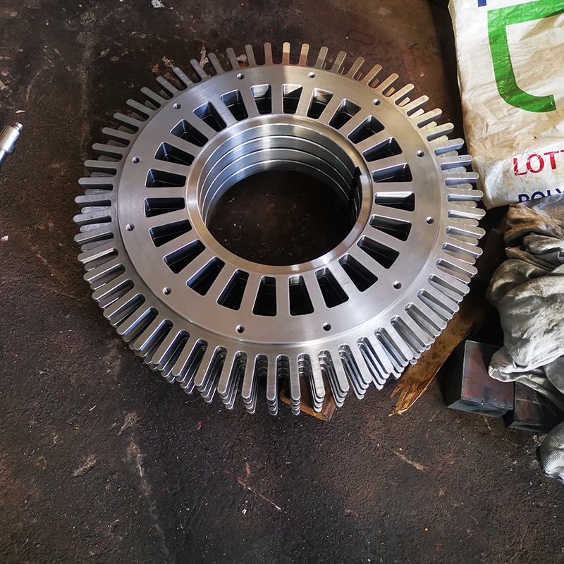
Processing method: CNC machine processing, laser welding
Quality inspection: ultrasonic testing, magnetic particle testing, water pressure test
Ship depth measurement system
Pipeline system for measuring the height of liquid in compartments and liquid tanks
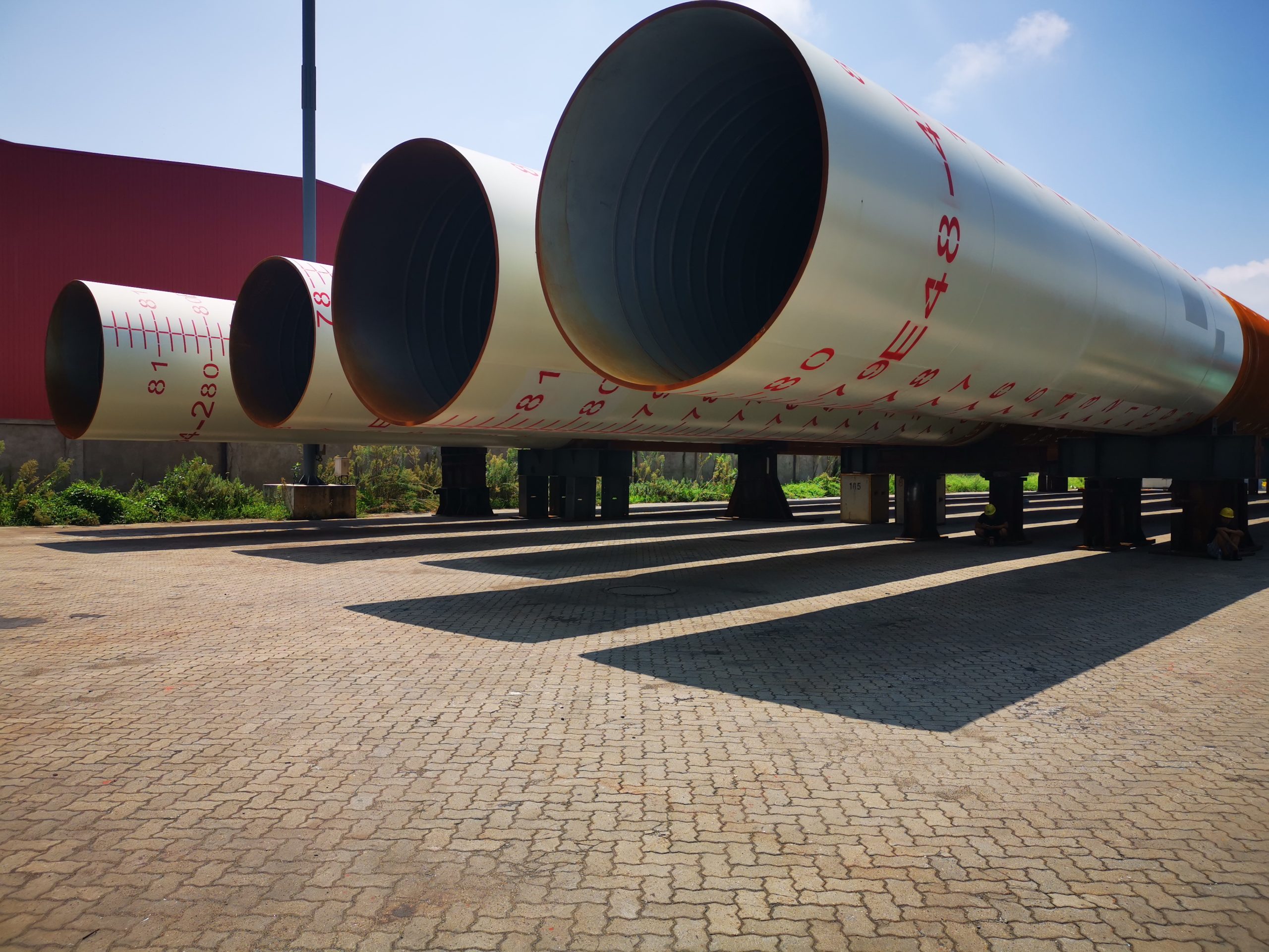
The ship depth measurement system is a piping system used to measure the height of liquid in compartments and liquid tanks.
Design principles for ship depth measurement systems
Pipe arrangement
The lower end of the pipes of the ship’s depth measurement system should be arranged at the lowest point of the cabin.
The curvature of the pipe
The pipes of the ship’s depth measurement system should be straight pipes as much as possible. If it is necessary to use bent pipes, the curvature should not exceed 25 °.
Sealing of pipes
The lower end of the pipe of the ship’s depth measurement system should be slotted and sealed with an iron plate.
Surface treatment of pipes
The surface treatment method for the pipes of the ship’s depth measurement system is galvanization in the water tank and acid washing in the oil tank.
Work of ship depth measurement system
The pipes of the ship’s depth measurement system are usually sealed with copper caps. When measuring, a special wrench is used to open the sealing cap, and then the depth gauge is slowly lowered from the depth gauge to the bottom, and then shaken up to calculate the depth of the liquid in the tank based on the wet position displayed on the depth gauge.
1. Which compartments require sounding pipes?
According to the specifications, the depth measuring device should be installed in the liquid tank and all compartments that are not easily accessible. For example, all oil and water tanks, isolation voids, pipe tunnels, and sewage wells that are not easily accessible should be equipped with sounding pipes. Measure the tube as close as possible to the suction port. For drinking water tanks, some shipowners, due to hygiene requirements, do not install sounding pipes and instead equip other measuring devices. If using a bubble measuring device, a pressure converter should be used to prevent compressed air from coming into direct contact with drinking water.
Usually, the end of the sounding tube terminates at an easily accessible location above the bulkhead deck or freeboard deck, and is equipped with an effective permanently attached metal closing device. Last week, a friend in the group asked what material is needed for the cover of the sounding tube? If you look at the classification society regulations, it should not be difficult to answer. According to industry standards, there are three types of measuring heads, namely A-type (steel deck) and B-type (wooden deck) installed flush with the deck, and C-type (raised type)
However, in machine spaces and shaft tunnels, it is not practical for the sounding pipe to terminate above the bulkhead deck or freeboard deck. Therefore, regulations allow for a shorter sounding pipe to be led to an accessible location above the flower steel plate and equipped with an effective closing device. Generally, the distance between the short sounding pipe head and the flower steel plate is about 800 mm to 1 meter
2. Special arrangement of sounding pipes for flammable oil tanks
There is a requirement in conventions and regulations that the end of a depth measuring pipe used for fuel (excluding lubricating oil) should be terminated in an open atmosphere, where there is no risk of overflow from the depth measuring pipe and fire. Especially, its terminals should not be located in the cabin or passenger compartment. I remember Liu Laogui once told a case where a bulk carrier in Japan, Zhan Xiaomu, was undergoing PSC inspection and found that the sounding pipe of the heavy oil tank was terminated in the aisle of the main deck living area,
Usually, the sounding tube cannot be terminated at the machine location. If the classification society finds it difficult to achieve, the end of the sounding pipe can be placed in the machine room, but three special requirements must be met:
Additionally, install a liquid level gauge that meets the requirements.
Unless there are measures, such as effective shielding, to ensure that the fuel overflowing from the sounding pipe does not come into contact with the ignition source, the end of the sounding pipe should be kept away from the fire hazard area.
The depth measuring tube terminal is equipped with a self closing blind break device and a small diameter self closing control cock, which should be located below the blind break device to ensure that there is no fuel overflow before the blind break device is opened. Corresponding measures should also be taken to ensure that the fuel overflowing from the plug does not flow into the fire hazard area,
However, for oil and fuel discharge tanks smaller than 2m3, the level gauges and control cocks mentioned above can be exempted if suitable shut-off devices are installed on the sounding pipe,
3. Layout details of sounding pipes
Sounding tubes are usually straight tubes, but many small boats have larger curvature at the bilge, and the sounding tubes must extend as far as possible to the bottom of the hold, forcing them to bend.
If bending is necessary, the curvature radius should be as small as possible to make it easier for the depth measuring instrument to pass through. For cargo ships, curved sounding pipes through other compartments should be given special consideration by the classification society. This arrangement is usually only feasible when the compartment passing through is an isolated empty compartment or when there is the same liquid stored in the compartment of the sounding tube. The curved part of the sounding pipe should be thickened and supported appropriately, but the classification society’s regulations do not require a significant tilt angle. Some shipyards’ process manuals mention a maximum of 15 ° for reference only.
Taking BV specification as an example, the inner diameter of the depth measuring tube should not be less than 32 mm. For sounding pipes passing through refrigerated areas or insulated areas where the temperature may be below 0 ℃, the inner diameter should be at least 60 mm. Other classification society regulations also require an inner diameter of 65 mm, with slight differences.
A cover plate should be installed at the lowest point of the measuring tube to prevent damage to the hull. When using bottom sealed measuring tubes, the sealing plate should be appropriately reinforced. In addition, for some ships where the sampling of ballast water is completed through a depth measuring tube, please pay attention to the position of the depth measuring tube groove and open several more holes along the length direction to ensure better mixing of ballast water in the depth measuring tube. According to some ship practices, the use of overflow method to replace ballast water has been proven to be effective for sounding pipes with fewer openings in the entire length. During the replacement of ballast water, the water in the pipes is not affected. Additionally, when the ballast tank is emptied and refilled, the ballast water remains in the pipes due to the vacuum effect inside the sounding pipes. Therefore, it is recommended that shipyards open as many holes as possible when making sounding pipes, in order to facilitate the full mixing of ballast water in the pipes and water in the tanks.
Contact Information for Depth Measurement Pipes Inquiries
For more information about Depth Measurement Pipes or to obtain customized solutions, please contact us:
Contact Person: Frank
Tel: 86-510-82305188-8060
Mobile: 86-18605101203
Mail: frankgu@cmecwuxi.com
Address: 15-16F, Building A10, No. 777, JianZhu West Road, Binhu District, Wuxi, Jiangsu, 214072. P.R. China
We look forward to collaborating with you and providing robust support and services for your business.


